
Project
PLTW engineering notebook — Mousetrap car
How can a mousetrap-powered car stop near 25 feet without giving up too much speed?
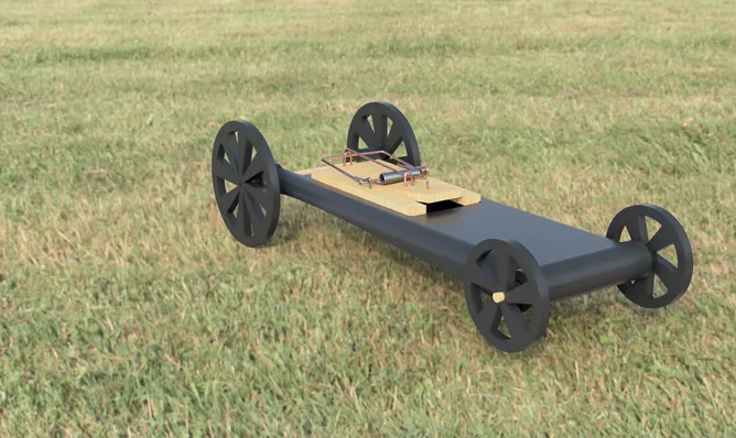
I adapted my eight-page PLTW Engineering Design and Development notebook into this project account. The original engineering notebook is available as a PDF, including the sketches, photographs, calculations, and full trial chart.
The brief
The assignment was to make a rolling vehicle powered only by a mousetrap. It had to travel at least 15 feet and stop as close to 25 feet as possible, as quickly as possible. I documented our group's initial sketches, printed parts, failed brake idea, and ten recorded distance trials.
Building the car
We iterated on a printed lever arm for the trap. It needed enough length to pull the car effectively without becoming so thin or long that it snapped when printed. For the axles, we chose wooden dowels over the supplied square VEX axles, then made D-shaped holes in the wheel hubs and flattened matching spots on the dowels so the wheels could turn with the axles.
Friction was another early problem. Bearings were too expensive for the project, so we used steel spacers where the axles passed through the chassis and graphite powder as a lubricant. The first design traveled about 40 feet on average, well past the target. We moved the trap forward and cut weight from the printed chassis with openings; the revised chassis weighed 43.22 grams. Small test prints helped us establish a press fit for the steel parts before printing the second chassis.
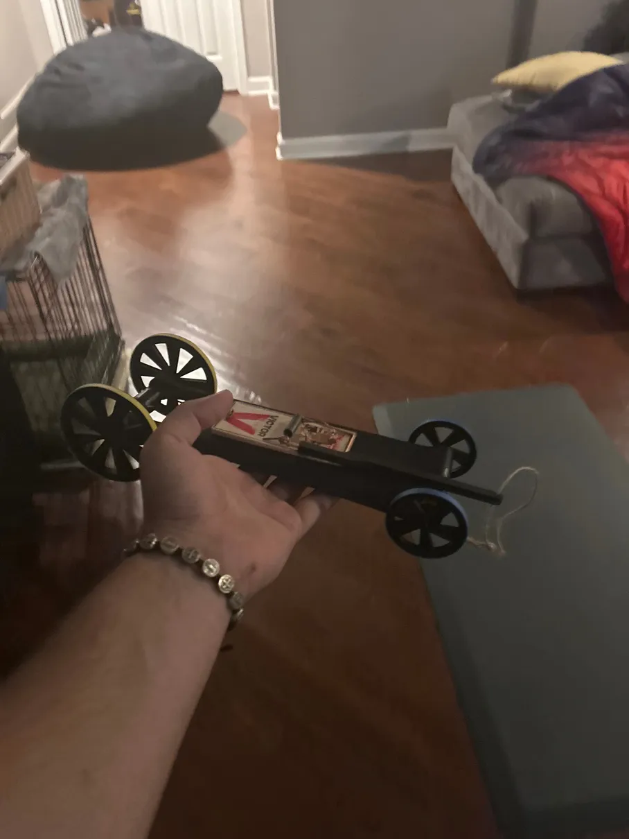
The car during construction, photographed for the original notebook.
A brake that did not make the final car
Because the car overshot the target, we tried an axle-driven threaded stopper. With a 2-inch rear wheel, traveling 25 feet would turn the wheel about 47.8 times. At 24 threads per inch, a nut on the axle would move about 1.99 inches over that distance. That gave us a starting length for the printed brake.
The first threaded print was too tight to move reliably. I loosened the thread fit in CAD and offset the thread faces by 0.05 inches, which produced mating parts. The mechanism still proved too fragile for the final vehicle: the rear axle broke after the car was bumped, and the repair removed the grooved guide used by the stopper. We did not use the threaded brake on the final car.
Testing and result
We tuned the length of string pulled by the trap with stopper knots. The notebook records these ten distances:
| Trial | Distance (feet) | Trial | Distance (feet) |
|---|---|---|---|
| 1 | 24 | 6 | 25 |
| 2 | 25.5 | 7 | 25 |
| 3 | 24.5 | 8 | 24.5 |
| 4 | 24 | 9 | 26 |
| 5 | 25 | 10 | 25 |
Four trials stopped at 25 feet, and all ten fell between 24 and 26 feet. After the first five trials, we changed from aligning and measuring at the front wheel to using the rear wheel, so the distances are best read as evidence of tuning rather than a single uniform measurement protocol. Although speed was part of the assignment, we did not record trial times in the notebook.
What I learned
I learned more from testing the parts than from calculating the brake. A dimension that looked right in CAD might be too tight once printed. Wheel alignment, friction, trap force, and the strength of a repaired axle changed what the car actually did. Repeated trials let us make specific adjustments and approach the 25-foot target with the mechanism we could make reliably.